


Alto Speakers
NOTICE - ALTO REPAIRS. 20th March 2025
We will continue to post information on what we have repaired to help those who want to either repair themselves or use a different Engineer.
During our research we also discovered a good Engineer based in Torquay who seems to have experience with Alto, so maybe give them a try too. See here.
It seems Alto do not want to support third party service centres and want a monopoly on servicing of their units. So, you have the option to contact Alto or use many of the technically competent engineers elsewhere and we will post as much information as we can to support all these and hopefully save you money.
We recently repaired 2 Alto Powered speakers which seemingly had exactly the same issue.
There are 3 Boards to the amplifier, two are located to the rear of the input sockets and a main PSU and PA section which is on one large PCB in a metal case.
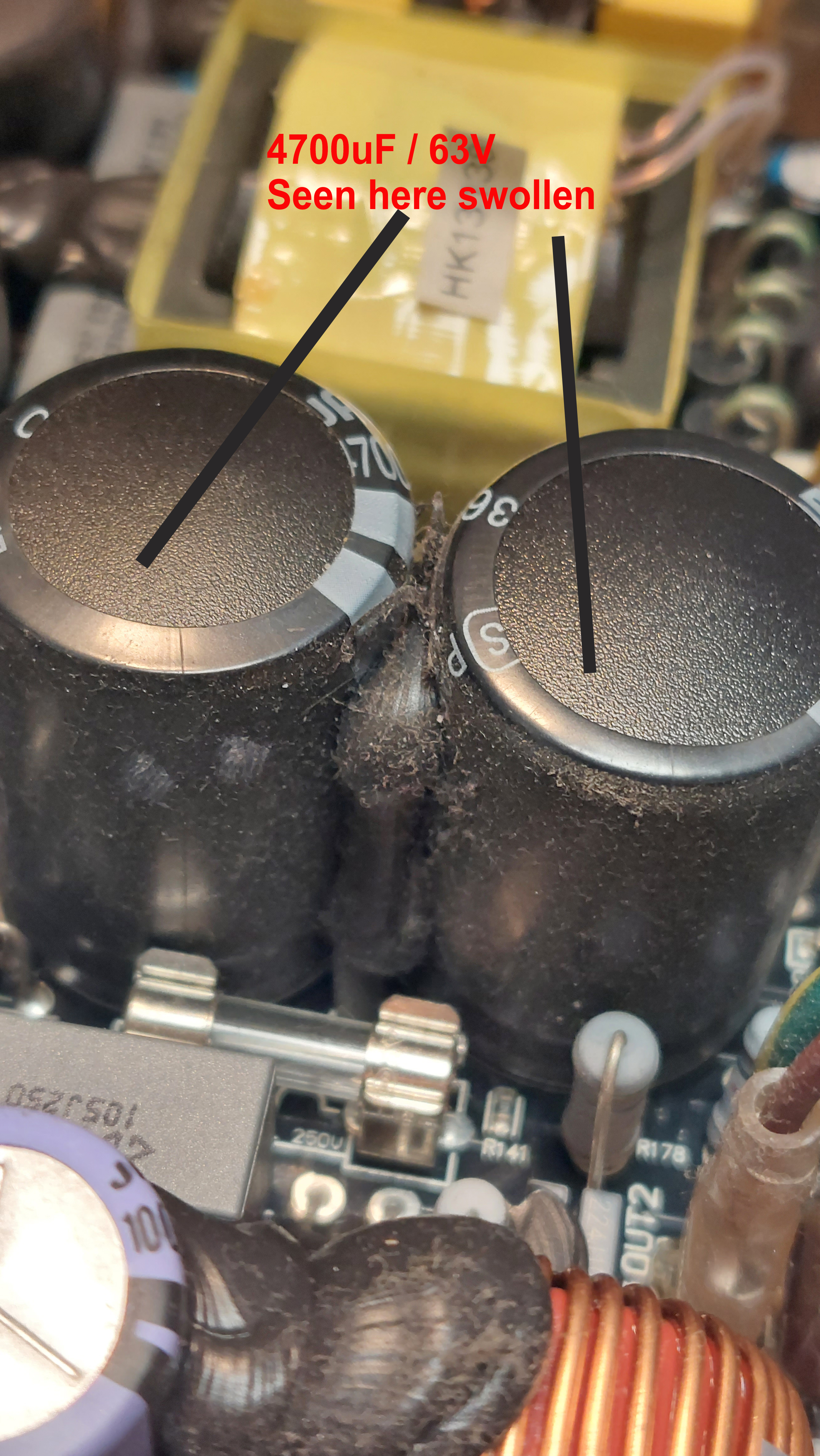
On the Power Supply Main PA section, the main electrolytic Capacitors had swollen and probably gone short circuit. Without spending hours/days reverse engineering the circuit layout to a schematic I can't be too sure if these capacitors are in the Power Supply section or the PA section. I suspect they are part of the PA section - 4700uF/63V.
As a preventative measure and precaution we also changed the capacitors which are definitely in the PSU section. 470uF/180V although we used 200V instead.It is with regret that we are unable to repair any ALTO products, with immediate effect. This is under our commitments under PAS7050 for product safety.
As Alto do not give out any information on parts or schematics, we are unsure of the specifications of some parts and therefore cannot positively ensure the safety of these products even though we will always overate any component alternative ( ie a 180V rated capacitor will likely be replaced with a 200V rated one).

Our measurements indicated that there is a +60V and -60V rail for the Class D Amplifier section, which (again more guesswork than studying schematics which were unavailable) are fed by a lower powered PA IC to a pair of FET to drive the speaker(s).
There is also a +15V and -15V rail from the PSU section which also feeds the separate Input PCB.
Our experience showed that the +15 Regulator had also blown up on all units serviced - albeit chicken/egg scenario as to what caused what to blow. A standard TO220 +15 Regulator (ideally a 2A rated one) should get all rails working again, and the Voltages can be crudely measured on the main PCB on the 3 pin molex connector shown below with -15V/ Ground / +15V.
The +60V and -60V can be measured on the GLASS FUSES as indicated, but BE CAREFUL as 60V can still be lethal.
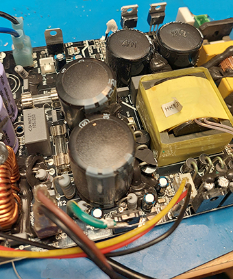
The image above shows the 15V cable, with Yellow, Black and Red wires coming from it, which goes to the Mixer/Input PCB and should measure at +15 and -15V. The associated +15V and -15V regulators are located next to this molex connector.
The +60V and -60 rails can be measured on the glass fuses also seen in the above image. You can also see the swollen 4700uF Caps in this image.
CAUTION
As already mentioned there are high voltages present on this PCB. Under no circumstances should an amateur attempt repair as the voltages are lethal in some sections.
If you are qualified and or experienced to do such repairs as an additional caution - most of the TO220 devices and the pre-driver AMP IC have insulators on them - so be careful to ensure that they are re-assembled correctly.
We would love to hear feedback from you on this new section of our website, to see if its worth adding more tips.
Please either email: sales@red-radio.co.uk or use the contact form in the contact us section.
Thank you
John
Back to PA Speaker Repairs Back